Phys5
LIGHT
Reflection of Light

Laws of Reflection
-angle of incidence (i) = angle of reflection (r) , i = r
-incident ray, reflected ray & normal at pt. of incidence, all lie in same plane
Experiment 1: To Verify the Laws of Reflection of Light
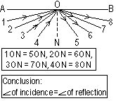
Draw a line AB on a sheet of paper
Mark mid-point O > perpendicular line ON
measure out 6 angles from ON
Place reflecting surface of mirror on AB
Ray Method;-Shine a narrow ray of light along one of the lines onto the mirror
Pin Method;- put pins 1 and 2 on a line, insert sighting pins 3 and 4 so that they are inline w/ images of 1 and 2 in mirror
Mark position of reflected ray > measure angle of reflection
Properties of the image in a plane mirror
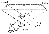
1-same size
2-virtual
3-laterally inverted
4-same dist behind mirror as the object is in front of it
(+line joining object and image is perpendicular to mirror)
Refraction of Light
Refraction-bending of light as it travels from 1 medium to another, at a glancing angle due to change in speed of light in different media
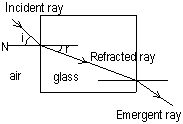
Enters a optically denser medium-bends towards normal
Enters a optically less denser medium-bends away from normal
Emergent ray from a parallel-sided block is parallel to incident ray
Light travels along normal; no refraction
Conditions of refraction
-a boundary bet. 2 media of different optical density
-incident ray is incident obliquely to boundary (incident ray must not be travelling along normal)

Laws of Refraction
-incident and refracted rays are on opp sides of normal at the pt of incidence and all 3 are in the same plane

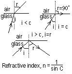
-Snell's Law; ratio of the sine of the angle of incidence to the sine of the angle of refraction is a constant for a pair of media and is called the refractive index, e.g. airn glass = 1.5, airn water = 4/3, vaccuum; n = 1
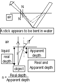
Refractive Index, n = ratio of speed of light in air to speed in other medium

Some effects of refraction
Critical Angle
When light passes from 1 medium into an optically less dense medium, at a certain angle of incidence, angle of refraction = 90O
This angle of incidence = the critical angle, when i > c, total internal reflection
Light pipe/Optical fibre
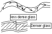
Advantage of TIF: no loss in light intensity, used by doctors and engineers to light up awkward spots. in telecommunication, pulses of light representing info (telephone conversations, computer data) are conveyed through optical fibres
Conditions for Total Internal Reflection
-angle of incidence > critical angle
-rays travelling from an optically denser medium to an optically less dense medium
Dispersion of Light
Dispersion of light by a prism- splitting up of a light beam into component colours; produces a spectrum

White light consists of 7 colours; ROYGBIV, red deviates the least, violet the most, due to diff refractive index of each colour in glass, monochromatic light-light of 1 colour
A 2nd prism can be used to split up the colours even further
The colours of the spectrum can be recombined to form white light when a 2nd prism is used to make it like a parallel-sided glass block, which doesn't produce dispersion
Lenses
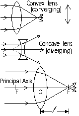
Centre of lens, C- optical centre, line through C, at a right angle to lens = principal axis
A beam of light parallel to the principal axis is refracted and converges w/ principal axis at a pt = principal focus, F
f = focal length of lens
Determination of the focal length of a converging lens
Object = hole & cross wire (for sharper image), lens; adjusted until sharp image formed on screen, focal length = f
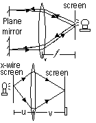
Lens; adjusted until a sharp image formed on screen
[using the convention: real is +ve] 1/v + 1/u = 1/f
Ray Diagrams

draw a ray
-parallel to principal axis which is refracted through principal focus, F
-through optical centre C which is undeviated (for a thin lens)
object beyond 2F, image-real, inverted, diminished, between F & 2F opp side, camera
object at 2F, image-real, inverted, same size , at 2F opp side, photocopier
object between 2F & F, image-real, inverted, magnified , between 3F & 4F opp side, slide / overhead projector
object between F & C, image-virtual, upright, magnified, behind object, magnifying glass
real image; image captured on screen, formed by intersection of light rays
virtual image; cant be captured on screen, no light rays reach pt where image is located
Magnification (m)
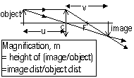
Electromagnetic spectrum
Features
-transfer energy from 1 place to another
-transverse, electromagnetic waves
-can travel through vacuums
-travel at speed of light (3 x 10⁸ m/s)
-show wave properties; reflection + refraction
-obey wave equation v = fλ
Highest > lowest frequency
Gamma rays > x-rays > ultra-violet > visible light > infra-red > radio
Gamma Rays
-from radioactive substances
-detected by Geiger Muller Tube, GM tube and counter
-penetrates through most materials except thick lead sheets or very dense concrete
uses: cancer treatment, detecting flaws in metal castings
X-rays
-from x-ray tubes
-detected by photographic paper or plates, photoelectic effect
-X-ray films bones will absorb most of the x-ray whilst the flesh will allow them to pass through
uses: radiography, detecting flaws in metals
Ultra-violet
-from mercury vapour lamps, sun
-detected by photographic film (produces fluorescence in certain salts)
-has tanning effects on the skin
uses: detects forgery, burglar alarms, sterilising (kills micro-org)
Visible light
-from incandescent objects
-detected by photographic film, eye
-easily scattered by mist + fog
uses: vision
Infra-red
-from hot bodies
-detected by phototransistor, thermopile phototransistor
-not easily scattered by mist or fog
uses: infra-red (night) photography, thermal photocopy
Radio waves
-from radio transmitting equipment
-detected by radio antenna or aerials
-reflected by ionosphere in upper atmosphere, passes through bricks & concrete
uses: broadcasting, communication
Magnetism
Electrostatic Charging
Electricity
Thermal Physics
Waves & Sound
Radioactivity
Measurements in Physics
Forces
Energy
Pressure
Back to 'O' level notes index
Back to notes index


