ALTERNATING CURRENTS
AC or alternating emf values vary periodically w/ time in magnitude & direction

1 complete alternation = 1 cycle
# of cycles in a second = freq
sine curve AC; ξ = ξ0sinωt

Power in a resistance circuit
av. I / emf of AC = 0 (for complete cycle)

rms (root mean square) / effective value of AC = steady I (DC) which produces same heating effect as the AC in a given R

sinusoidal AC: I = I0sinωt = I0sin2πft
P = IDC2R = (mean of IAC2) × R
IDC2 = mean of IAC2 => IDC = √(mean of IAC2) = Irms
Irms = √(mean of I02sin2ωωt) = I0√(mean of sin2ωt)

from graph: mean of sin2ωt = ½
Irms = I0√(½) = I0/√2 = 0.707 I0
mean P of R = ½Pmax of AC (P = I2R = Irms2R = ½I02R)
Simple transformers

-consists of 2 coil wound onto Fe core
-used to change voltages
AC supply => changing mag flux in Fe core => Vinduced on secondary coil
ideal: VS/VP = NS/NP
Pinput = Poutput => IPVP = ISVS
VS/VP = NS/NP = IP/IS
electricity transmitted over long dist > R in cables > energy loss
min E loss: high V, low I => substation step-up V (to 220000V) before transmission => step-down before used (240V)
high V: more efficient but dangerous => needs good insulation
Rectification of AC (AC > DC)
rectifier (diode)  : low R in 1 direction (forward direction, forward bias), high R in other direction (reverse direction, reverse bias)
Half wave rectification


1st half cycle: forward dirn => I pulses in output (pdout pdinput, slight R)
2nd half cycle: reverse dirn => v.little/ no I pulses in output
I unidirectional => pdout direct (only fluctuates, doesn't change dirn)
Full wave rectification


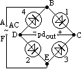
4 diodes arranged in bridge network
A: +ve => 1,2 conduct (D > B doesn't occur as potential at D is less than potential at B)
(ABC > pdout > DEF)
A: -ve => 3,4 conduct (FEC > pdout > DBA)
both halves of pdinput converted to pdout in same dirn
Iout unidirectional, but pdout varies from max to 0
to obtain more steady DC output, use smoothing circuit
Smoothing circuit


-use reservoir capacitor (large capacitor, >= 10µF)
OA: capacitor charged to almost peak V while VR ^ to peak V
at A: input pd decreases below VC => capacitor discharges through load (not through rectified pd as wrong polarity)
at B: input pd = value V1 has fallen to => capacitor quickly charged, VR ^ to peak => cycle repeats
larger capacitor => better smoothing (VR falls less) but initially uncharged capacitor acts like a short circuit => I surge => can damage rectifier
Back to 'A' level notes index
Back to notes index


 : low R in 1 direction (forward direction, forward bias), high R in other direction (reverse direction, reverse bias)


